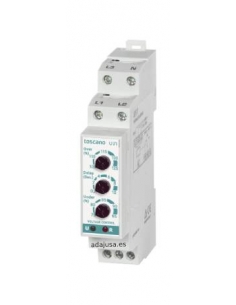
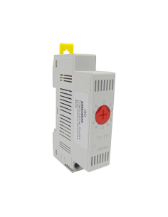
Electronic relay for monitoring the current flowing through its measuring circuit, if the measured current is within the set parameters the relay R switches on.
This relay is usually used to protect machines against overloads or idle operation of machinery or electrical circuits, associated with contactors or circuit breakers, or by direct control of the same.
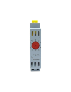
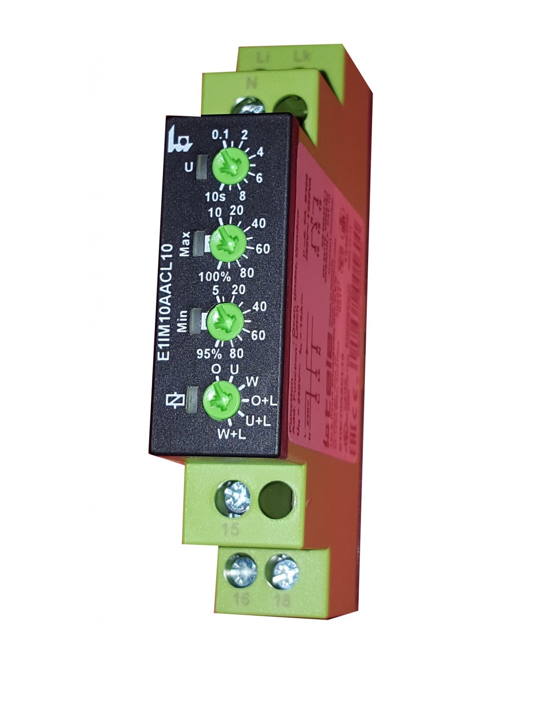
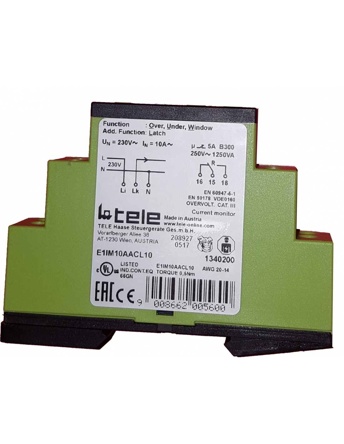
The relay is designed to work on single-phase alternating current lines, with a supply voltage of 240Vac and a maximum current of 10A.
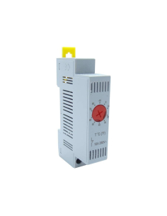
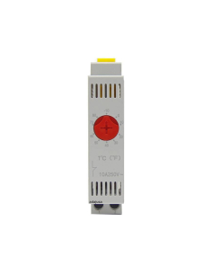
The width of the relay is 17.5mm and all adjustments are made from the front of the relay.
Description of Operation:
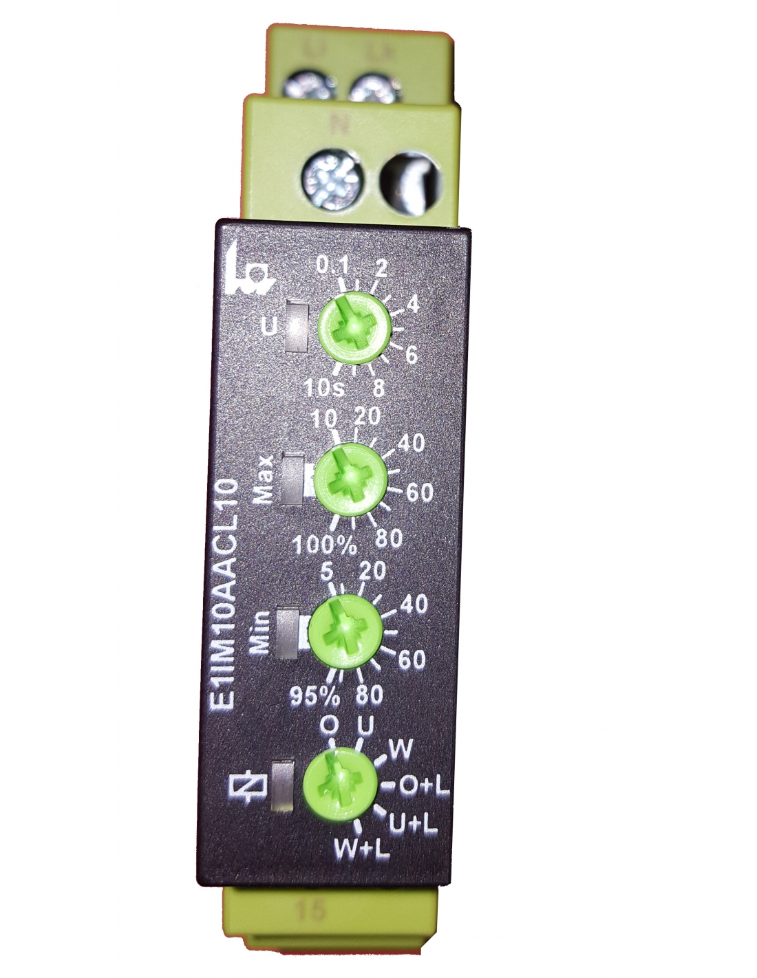
When the supply voltage is applied the output relay R is activated, if the measured current is within the set parameters, the yellow LED lights up. If at any time the current does not remain within the setting range for longer than the time set on the time delay setting potentiometer (marked U) the output relay is deactivated.
Depending on the relay configuration, if the current returns to within the set values, the output relay may or may not re-energize.
Six modes of operation are available:
- Maximum intensity control with automatic reset (O).
- Maximum intensity control without automatic reset (O+L).
- Undercurrent control with automatic reset (U).
- Undercurrent control without automatic reset (U+L).
- Maximum and minimum intensity control with automatic reset (W).
- Maximum and minimum intensity control without automatic reset (W+L).
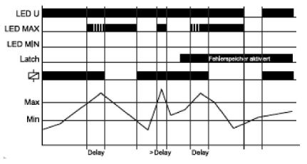
Maximum intensity control (O, O+L).
When the current flowing in the circuit exceeds the value set on the potentiometer MAX (10..100%). When the current exceeds the set value, the tripping delay time (Delay) starts, the tripping time can be set with the potentiometer marked U and is adjustable between 0.1 and 10s. At the end of the delay time, the output relay is switched off, the yellow LED goes out and the red LED remains illuminated.
During the Delay time, the red LED will remain flashing.
If the O function has been selected, when the current returns to a value within the range, the output relay will be switched on again, if the O+L memory function has been selected, the output relay will remain switched off after a trip even if the current returns to a value within the setting range. Only after resetting the fault (by switching the auxiliary supply voltage off and on again) will the output relay switch back on.
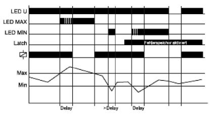
Undercurrent control (U, U+L).
When the current flowing in the circuit falls below the value set on the MIN potentiometer (5..95%). When the current falls below the set value, the tripping delay time (Delay) starts, the tripping time can be set by the potentiometer marked U and is adjustable between 0.1 and 10s. At the end of the delay time, the output relay is switched off, the yellow LED goes out and the red LED remains illuminated.
During the Delay time, the red LED will remain flashing.
If the U function has been selected, when the current returns to a value within the range, the output relay will be switched on again, if the U+L function with memory has been selected, the output relay will remain switched off after a trip even if the current returns to a value within the setting range. Only after resetting the fault (by switching the auxiliary supply voltage off and on again) will the output relay switch back on.
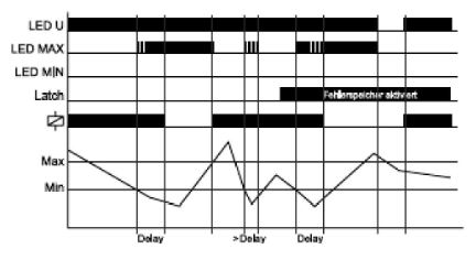
Maximum and minimum intensity control (W, W+L).
The output relay R will remain switched on (yellow LED illuminated), as long as the current is between the MAX and MIN values set on the potentiometers.
When the current flowing in the circuit exceeds the MAX current set at the MAX potentiometer (10..100%) or falls below the value set at the MIN potentiometer (5..95%), and exceeds the tripping delay time (Delay), the tripping time can be set by the potentiometer marked U and is adjustable between 0.1 and 10s. At the end of the delay time, the output relay is switched off, the yellow LED goes out and the red LED remains illuminated.
During the Delay time, the red LED will remain flashing.
If the W function has been selected, when the current returns to a value within the range, the output relay will be switched on again, if the W+L function with memory has been selected, the output relay will remain switched off after a trip even if the current returns to a value within the setting range. Only after resetting the fault (by switching the auxiliary supply voltage off and on again), the output relay will switch back on.
Technical characteristics.
- Manufacturer: TELE
- Reference: E1IM10AACL10 230VAC
- Power supply voltage: 230Vac (Li-N)
- Permissible tolerance: 0.85..1.15 Un.
- Nominal consumption: 2VA.
- Nominal frequency: 48..63Hz.
- Connection time: 100%.
- Reset time: 500 ms.
- Waveform: sinusoidal.
- De-excitation voltage: >20% of supply voltage.
- Overvoltage category: III (according to IEC 60664-1).
- Permissible impulse voltage: 4 kV.
Timing scales:
- Trigger time (Delay): 0.1..10 s.
Signage:
- Green LED U/Ut: power supply (relay in operation).
- Green LED U/t flashing: Start-up inhibition.
- Red LEDs ON/OFF: on/off indication.
- Flashing red LEDs: Signaling of a defect during the tripping time.
- Yellow LED ON/OFF: relay output on/off.
Output circuit:
- number of contacts switched: 1NAC.
- Rated voltage: 250Vac.
- Switching capacity: 5A/250Vac.
- Fuse protection: 5A. Fast acting.
- Mechanical durability: 2x10⁶ maneuvers.
- Electrical durability: 5x10⁵ maneuvers, with 1000VA resistive load.
- Switching frequency: 60 man/min with 100VA.
Measurement circuit:
- Measured value: 10A alternating current (48..63 Hz).
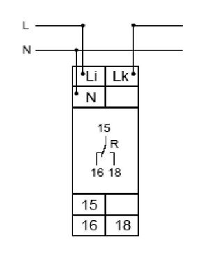
- Measurement input: Li-Lk terminals.
- Permissible overcurrent:
- Permanent: 13A (≥10A - distance >5mm).
- during 1s / 3s: 100A / 50A
- Input resistance: 3mΩ.
- Adjustable threshold values:
- Max: 10%..100% In.
- Min: 5%..95%.
Accuracy
- Basic accuracy: ±5% of nominal value.
- Setting accuracy: ±5% of full scale.
- Repeatability conditions under constant conditions: ≤2%.
- Influence of temperature: 0.05% per ºC.
Connection
Dimensions
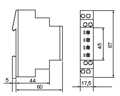
For further information you can download the data sheet by clicking on the "Attachments" tab.
Material for professional use, install in compliance with the regulations in force at the place of installation.


